


Bill-to-Bill™ E-Learning Chapters
Chapter 1.1: Bill-to-Bill Components
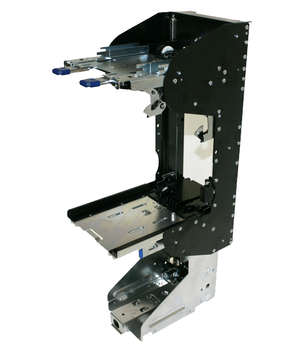
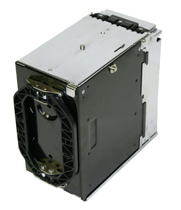
The Housing is the units' frame into which all other components are installed. The Housing also serves as a platform for installing the unit in an OEM cabinet and is the Bill-to-Bill's only module that is permanently secured inside of the cabinet.
The Housing does not contain any Sensors, CPU Boards or Motors.
Make sure that no foreign materials are present in the bill’s pathway before assembling the Bill to Bill components to the Housing.
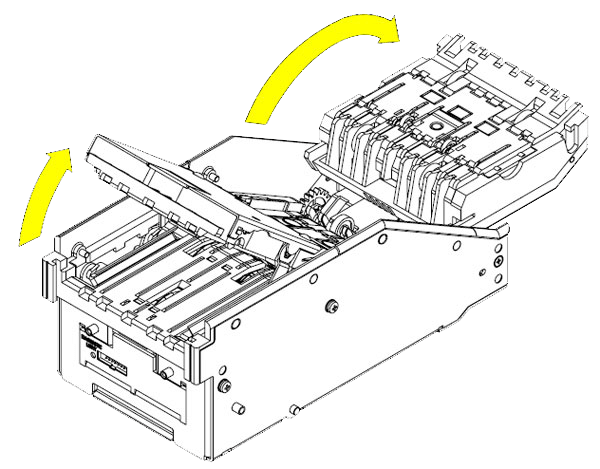
The Bill-to-Bill’s validating head features self-centering transport guides, which perfectly align multi-width and skewed bills and/or barcoded tickets. The width of the bill path automatically adjusts to accommodate each bill. There are two guides in the validating head that must be opened to access the bill path. If space above the Bill-to-Bill allows, the guides in the validating head can be opened without removing the validating head from the housing. Otherwise the validating head must be removed from the housing. Figure 2
To open the guides lift the latch on the top of each guide and rotate the guides as shown in Figure 3. There cannot be any scratches present on the guides and optical sensors, also there cannot be any cracks present on the visible surface of the transport rollers.
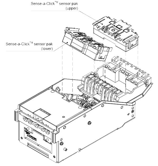
Sense-a-Click sensor packs are a set of two sensor modules — one upper and one lower. In order to be compatible with each other, both modules must have the same part and model number. Figure 4
The Sense-a-Click set is identified by its:
- Color and position of the optical sensors
- Number and position of the inductive sensors
- Model, which reflects the type of electronics housed therein, and determines the compatibility with other modules
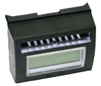
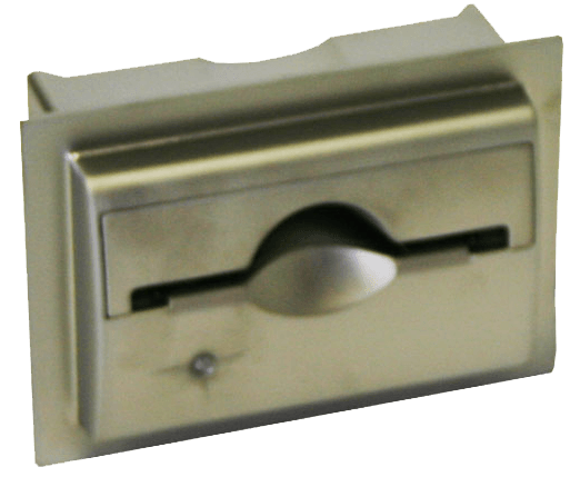
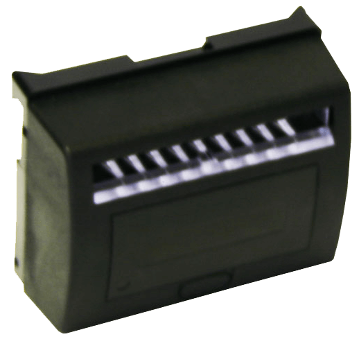
There are a number of bezels that can be used with the Suzo-Happ Bill-to-Bill™ Currency Management System. These bezels are shown here. It is recommended, however, to use the Suzo-Happ bezel with digital display. This option is a more convenient way to manually control the Bill-to-Bill (i.e.: software updates, diagnostics, unloading, etc.).
Several bezel designs are available from Suzo-Happ in order to make the Bill-to-Bill compatible with different door styles. Typically the Bill-to-Bill is supplied with a standard bezel featuring runway lights and a digital display. The bezel is permanently attached to the validating head.
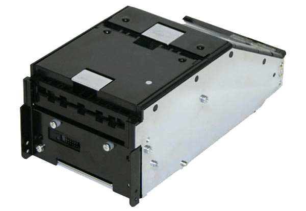
After the bill is successfully validated from the Validating Head it goes to the Chassis where, with assistance of the Path Switch is stored in one of the Cassettes — Dispensing Cassette, Recycling Cassette (1, 2, 3) or Drop Cassette.
The Chassis is the Bill to Bill component where each of the three Recycling Cassettes and the Dispenser, figure 8, are installed. To open the Chassis press release button and pull open the Chassis. The gas spring supports the chassis in the opened position, see video 1. The opened chassis also allows access to the path switch. The chassis can be opened with, or without, the recycling and dispensing cassettes present.
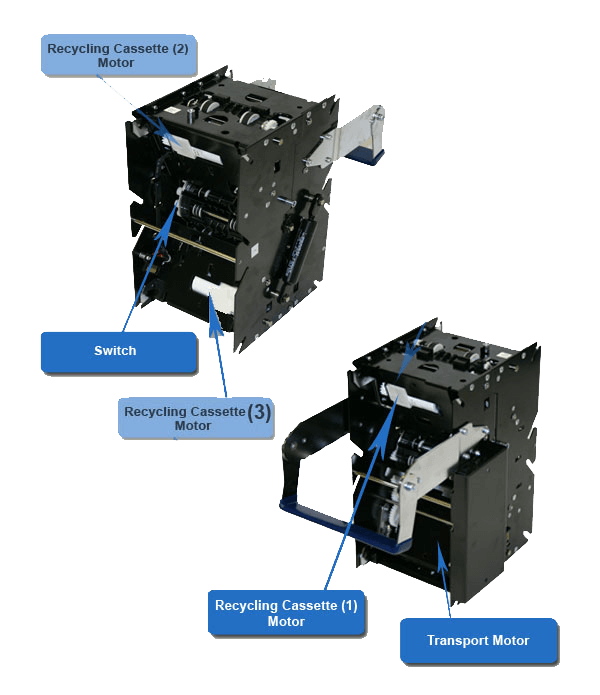
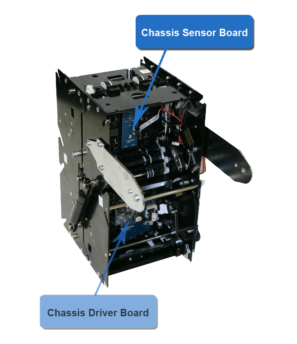
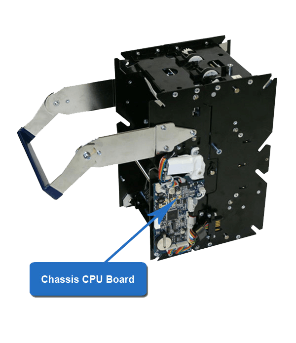
The Chassis contains two sensors boards and two light guide assemblies which are located under the bill path, figure 9, it also contains a main CPU board which is located under the black cover, see figure 10, and four motors for each cassette — Dispensing Cassette and Recycling Cassette (1, 2, 3). figure 7
For best performance clean the bill path and make sure that no foreign materials, dust, dirt or scratches are present on the Chassis’s sensors area, see video 2.
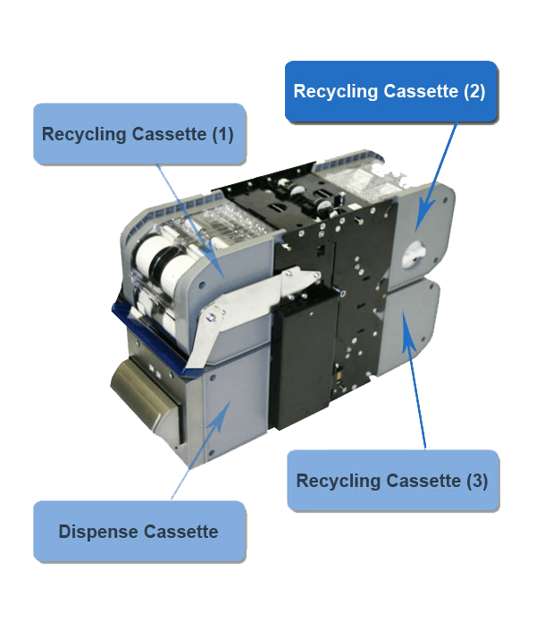
The Bill-to-Bill unit carries up to three recycling cassettes, which operate identically. The Recycling Cassette is designed for storing the bills which can recycled and given as a change to next costumer. Built with flexibility in mind, the user can program which bill denominations will be used in each of the recycling cassettes..
The maximum storage capacity of each cassette ranges from 80 to 110 bills. The exact number of bills that can be stored is dependent upon the bill length: the shorter the bill, the higher the number of bills that can be placed inside the cassette. A flash memory inside each recycling cassette stores information on the number, and denomination of bills housed in the cassette. The flash memory prevents operation errors from occurring, i.e. — when a cassette is installed in a random position in the Bill-to-Bill. Bills can be manually dispensed by rotating the plastic knob in counter clockwise direction. Bills are manually dispensed one bill at a time. Should a jammed bill be located in the entrance slot, the bill can be easily removed without adversely affecting the later operation of the cassette.
Please note: manually unloading bills will reduce the number of bills in the cassette, without changing the number of bills in flash memory. It is strongly recommended to perform a complete unload operation, after the cassette is replaced in the Bill-to-Bill. A recycling cassette can also be programmed to serve a multi-bill escrow cassette.
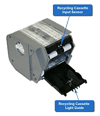
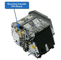
The Recycling cassette contains a main CPU Board which is located under the cover with no wheel — figure 12. Input Sensors Board located under the guide above the Cassette’s door and light guide located on the Cassette’s door figure 13. The Recycling Cassette does not contain any motors; cassette mechanism and is driven by the appropriate cassette motor which is installed on the chassis.
For optimal performance, there must not be any dust or dirt on the surface of the Input Optical Sensors. — see video 3
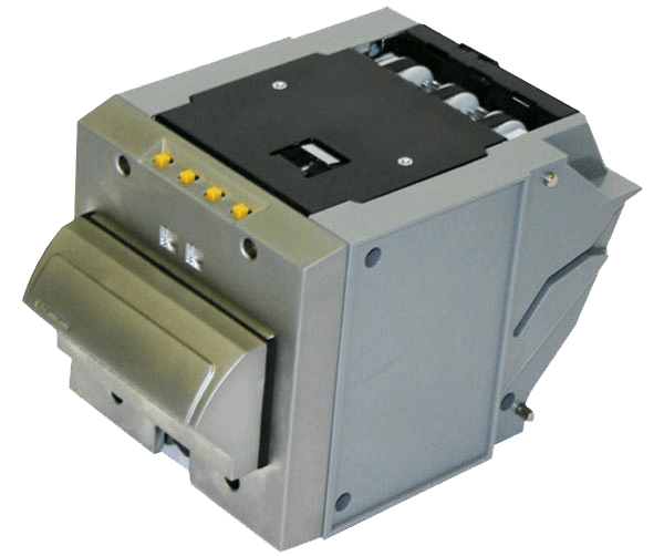
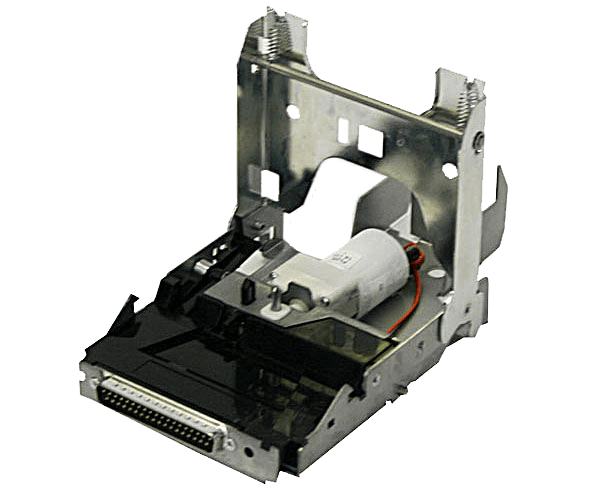
There is only one dispensing cassette in the Bill-to-Bill unit. In contrast to the three recycling cassettes, the dispenser has a permanent position in the chassis. The dispensing cassette can dispense a bundle of up to 20 bills at a time. Bills from all three recycling cassettes can be combined into one bundle. Should more than 20 bills need to be dispensed, then subsequent bundles will be delivered to the dispensing cassette once the previous bundle is removed. On the front side of the Dispenser is located the service keypad. A standard 3/4" tubular lock can be installed in the dispensing cassette, which will allow the chassis to be secured to the recycling cassette module, and the dispensing cassette inside the housing. There is a placement for a lock under the dispensing slot.
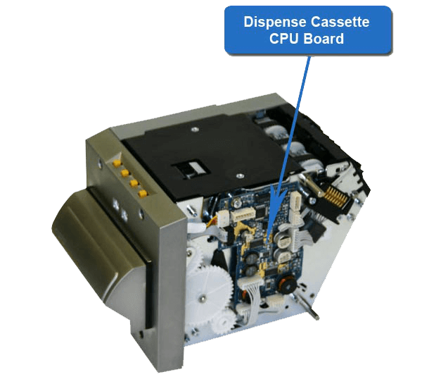
The Dispenser contains two motors which are located on the bottom of the Cassette under the black metal cover. The drums motor serves to rotate the Drums and stock the bills in the Dispense Cassette before they are dispensed. The shutter motor serves to open the shutter gate and dispense the bills. The Dispense Cassette also has three sensors boards and one main CPU Board, figure 15.
For best performance clean the Dispenser sensors and make sure that noting prevents the passage of the bills, see video 5.
The drop cassette stores validated bills and barcoded coupons and holds them in a stacked formation. The drop cassette has a stacking mechanism, and is equipped with a plastic lock. Users are encouraged to replace the plastic lock with a 3/4" tubular metal one. Users also have a choice between one lock — or two locks for added security.
A locking mechanism allows for the installation of a user’s security locks (specifically, one or two 3/4" tubular locks measuring 11/16”±1/16" or 11/8”±1/16"). The capacity of the drop cassette is 1000 bills. Street grade bills require more space and as a result, may lessen the overall capacity.
The drop cassette is supplied with a foldable handle, but where space inside the machine is limited, a premium drop cassette may be ordered without a handle. The drop cassette can store bills from 62 to 82 mm wide, and from 140 to 172 mm long. For bills from 125 to 150 mm in length, a modified drop cassette may be ordered. However, when accepted bills are 125 to 172 mm long, the drop cassette for 140-172 mm range must be chosen.
For best performance clean the Drop Box and make sure that the mechanism works properly. — see video 6
The Bill-to-Bill power interface module is placed in the housing at the left side of the validating head. It carries connectors for all external connections to the Bill-to-Bill. The Power Interface Module contains two sensors. For best performance make sure no foreign materials are present between the actuators. — Video 7
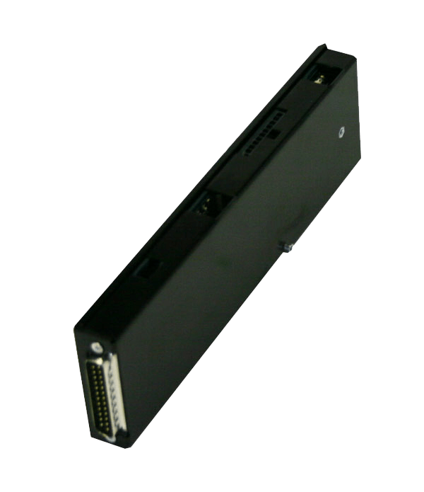
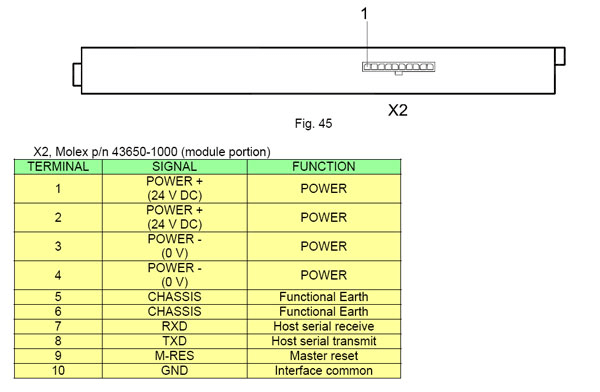
The Bill-to-Bill power interface module has the following external connections:
The Bill-to-Bill interface operates with RS232 levels and under CCNET protocol.
Download the B2B Interface PDF file
The length of the power and interface cables should not exceed 10 meters Power and interface cables do not connect to outdoor communication links and to outdoor DC current lines. Ensure all cables are shielded. The shield is connected to pin 6 of connector X2. The shield of another cable end is connected either to the frame of the Host or to the grounding bus or terminal of the automat near to Host Controller. Power cables must use the fourth core cable connected to pins 1, 2, 3 and 4 of connector X2. Each wire section should be not less AWG22. From the direction of the power supply the wires are connected in pairs.
© SUZOHAPP 2026. All rights reserved.